Table of content
 Introduction
While it's important that every component in a building or system works individually, it's how they all interact together that really matters. With Integrated Systems Testing (IST), the commissioning process are able to put these items to the test. They create simulated circumstances that trigger components and subsystems to (hopefully) act and perform how they're supposed to.
This guide will explain IST commissioning testing, how it works, why they're important, and some examples of these tests.
What is an IST Test?
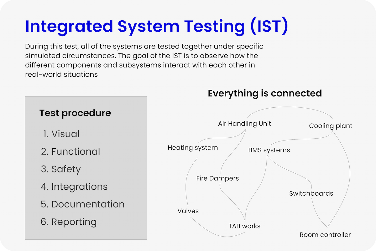
IST stands for Integrated Systems Test, and it refers to one of the last phases of commissioning testing. During this test, all of the systems are tested together under specific simulated circumstances. Also known as System Integration Testing (SIT), the goal of the IST is to observe how the different components and subsystems interact with each other in real-world situations.
In simplest terms, an IST ensures that all of the individual components in a building operate as they're designed to all at once.
The Difference Between FAT, SAT, and IST
The average building component goes through a series of tests before it is commissioned for use. These tests are commonly referred to as FAT, SAT, and IST, and they're each necessary during different phases of installation. We'll use a cooling plant as an example.
FAT, or Factory Acceptance Testing, occurs at the manufacturer's facility. The cooling plant is assembled and then tested to ensure that it works properly in the factory. Once a team of inspectors certifies that the plant passed the FAT procedure, it will be disassembled and shipped to the site.
SAT, or Site Acceptance Testing, occurs at the project site. The cooling plant will be installed on-site and connected to the appropriate systems. The component is then tested to ensure that it operates properly, free from defects or leaks.
IST, or Integrated System Testing, is the final phase. This is a building-wide test used to certify that all of the components within the building are working together properly. While this test would not be designed specifically for testing the cooling plant, the plant will be observed to ensure that it reacts properly to the given scenario. The goal is to ensure that the plant works with the building management system, electrical system, SCADA system, and other related components.
Examples of Types of Integrated System Testing
There are a few different types of ISTs, each with a set of conditions that the Cx team can simulate. These tests give the team the ability to observe the system in a variety of real-world scenarios.
Integrations (End-to-End)
Integration IST, also known as End-to-End, are designed to observe the normal operating conditions of the system. This would simulate typical operating conditions, with constant power, typical weather conditions, and standard draw and settings. This IST tests the interactions between the different systems and components to ensure they're operating as designed.
Performance Testing
Performance testing is an IST used to verify that the entire system is operating as efficiently and as stable as possible under various conditions. The test will be performed under various load or demand conditions to establish potential issues in systems that might otherwise go unnoticed.
Environmental
Environmental tests involve testing the system in various general use cases during weather extremes like winter and summer, and as such, they're difficult to simulate. Cx teams must wait for the correct weather conditions. For example, on a hot day, the team might lower the temperature in a room by 5 degrees and then observe the entire cooling sequence of the controller communicating with the BMS, the BMS communicating with the cooling plant and the air handler, and the VAV dampers.
Pull-the-Plug (Blackout)
The point of a pull-the-plug, blackout, or chaos test is to observe how all of the components in a system interact when all power is lost to the building. This event will trigger multiple systems, including the emergency power system's generators, emergency lighting, and alarms and notifications sent through the BMS and SCADA systems. The various components in the building designed to run on emergency power should continue to operate, and the different components should be able to reset back to the appropriate settings when the power is restored.
How To Perform an IST
Since the goal is to verify that all of the systems and their components work together correctly, an IST is all-encompassing. That can seem overwhelming, but it's helpful to break the process down into smaller sections.
Step 1: Prerequisites
Before an IST can start, there are a few things that need to be verified to ensure it's not a waste of time. For instance, it's important to ensure that all of the individual systems that will be part of the IST are operating correctly. If a system isn't communicating with the BMS system or the generators aren't fully functioning, a blackout test would be a complete waste of time. The IST process will result in failure since the inspector can't verify all of the systems performed correctly.
Don't start the IST commissioning process until all of the prerequisites are verified.
Step 2: Visual Inspection
After the prerequisites are verified, it's time to perform a visual inspection of the entire system. This process is important because it allows the CxA to identify any potential test-ending situations before the test starts. It's also a good opportunity to identify any small issues that allow the test to move forward but still need resolutions.
Consider two scenarios during a visual inspection. In the first scenario, the CxA notices that the equipment doesn't match the specifications on the building schematics. The test can't continue until the situation is rectified, whether that means updating the schematics or changing the equipment. In the second scenario, the equipment is missing a required label. The test can continue, but the label must then be installed before the equipment is fully commissioned.
In one scenario, we saved precious time and money by not performing a test that would ultimately not meet the commissioning standards. In the other scenario, we saved time and money by moving forward with a test but identifying an area that needs a resolution ASAP. This is the value of a visual inspection.
Step 3: Safety Inspection
Safety for everyone involved in the IST is of the utmost importance. The Cx team should perform a safety inspection outside of the visual inspection to ensure that the test will go as safely as possible. This is particularly critical for the Cx agent as they are responsible for system startups and shut-downs during the IST.
A safety inspection involves ensuring that all of the installation parameters are up to spec. In the case of emergency power, ensuring that cables are terminated correctly and then checking torque specifications to ensure they're installed according to spec would be part of the safety inspection. Ensuring that exhaust dampers and other safety devices are free to operate according to spec is also part of the safety inspection.
Once the mechanical components are verified to be working correctly, checking the system fail-safe sensors and relays is next. Ensuring that overload devices will protect components, that safety sensors will send the correct signals, and that alarms will activate will help keep the Cx team safe during the IST process.
Step 4: Functionality and Integration Testing
Step 4 is when the actual integration testing begins. At this point, the scenario can be simulated and all of the systems' actions can be observed.
As an all-encompassing test, it's vital to verify that everything is working according to spec. Following the chain of interactions from one system to the next and so on allows the Cx team to verify that everything is working, that all of the appropriate systems are communicating, and that all of the safety devices are operational.
For example, a blackout test might look like this:
- Turn off the switchboard and verify that the UPS is alerted.
- The UPS should send alarms. Verify the BMS/SCADA system is notified.
- The BMS/SCADA system should initiate multiple activities:
- Verify that one of these activities is sending the signal to the generators.
- The generators should receive the signal and start. Verify that they do before the UPS is drained.
- Verify that emergency and distress lighting turns on throughout the entire building.
- Verify that non-critical systems are turned off and remain off.
- Verify that critical systems remain operational throughout the test.
- Verify that one of these activities is sending the signal to the generators.
- Once the systems are checked and verified, ensure that all of the systems return to their normal settings upon power restoration.
Practical and Technical Test Items
The following are some examples of test items to inspect and verify. Every system is different so these are just general examples of common items.
- The TAB report has been approved.
- Trend logging must be set up on the ventilation system before the test begins.
- Ensure that components are located correctly across the system, PI diagram, and screen image.
- At a minimum, filters, damper positions, and temperature sensors should be checked.
- Labeling of system components is checked.
- Cable markers are checked.
- Pipe/channel marking is reviewed.
- Groups are marked with BMS addresses.
- The panel top is closed according to the IP class.
- Correct screws are used with a maximum of 1 cable per screw.
- Cables are mounted safely.
- The schedule is according to the specification.
- The position of the schedule in the software is checked, as well as any slave systems that may be connected.
- The setting of pressure switches is according to the supplier's instructions (values are often shown on the unit's rating plate).
- Software alarm limits are set as described in the function description (temperature, speed, etc.).
- The interval for each digital pressure sensor is checked.
- The K-value is checked.
- The settings of the digital flow meter are reviewed, and the K-value is compared.
- The installed filters are checked for filter type.
- It is evaluated whether new filters need to be inserted at delivery or whether new filters need to be placed next to the system.
- The filter is removed and inserted again to ensure it is correctly inserted.
- The system is set to normal operating mode.
- The frost sensor is affected by frost spray (use of a test button can be approved by CxA).
- The system mode changes to Freeze.
- The equipment for the heat valve and heat circulation equips to 100%, and the temperature of the heat plate increases.
- The frost alarm is transferred to the BMS as a high priority.
- The system is set in normal operation mode.
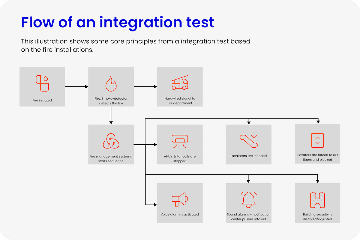
- A "short circuit" is performed on the fire thermostat.
- The system's mode changes to "Fire".
- The system shuts down and all related fire and smoke dampers close.
- The fire alarm is transferred to the BMS as a high priority.
- The system is set in normal operating mode.
- A "short circuit" is performed on the panel where the Automatic Fire Detection System IO module is mounted.
- The system's state changes to "Fire Detected".
- The system shuts down and all associated fire and smoke dampers close.
- The Automatic Fire Detection System alarm is transferred to the BMS as a high priority.
- All fire dampers are tested using the manual test button.
- Fire dampers fully close, and activating the end stop sends an alarm to the BMS.
- Fire dampers tested via BMS screen: Fire dampers activated via manually overridden from BMS.
- Weekly:
- When the fire dampers are closed, an alarm is transmitted to BMS.
- Weekly fire damper test: Fire damper test initiated via BMS.
- All brand dampers close.
- A report is generated for all dampers, showing that all are closed correctly.
- Automatic restart after voltage failure: The system is set to the "Operation" mode.
- The power supply to the system is interrupted and restored after 60 seconds.
- The system should start without delay in the last known operation mode ("Operation").
- Filter monitoring is tested via the filter pressure switches: The hose for the individual pressure switches is disassembled and suction is applied to create a pressure difference.
- Inspect rotor exchangers visually: Mounting of edge lists, brushes, motor hangers, and tensioning of spring.
- The spring that holds the motor-driven rotor should be slightly tensioned to compensate for belt wear.
- The rotor exchanger is manually run and checked:
- The set value for the rotor exchanger is set to 10%.
- The rotor exchanger is manually run and checked: The set value for the rotor exchanger is set to 50%.
- The rotor exchanger is manually run and checked: The set value for the rotor exchanger is set to 100%.
- The heat recovery function and sequence of the system are tested (recirculation - adjust to function description):
- The temperature setpoint is increased, which causes the recirculation to scale up to 100%.
- The equipment for the heat valve then starts, and heat is delivered.
- The CO2 setpoint is lowered below the current value, which causes the recirculation to ramp down and the rotor exchanger to ramp up.
- The CO2 setpoint is increased above the current value, which causes the recirculation to ramp up and the rotor exchanger to ramp down.
- The sequence for cooling is tested:
- The setpoint is changed to create a cooling demand.
- The heat valve, recirculation, and rotor exchanger stop/close.
- The cooling valve output increases.
- The intake temperature drops (may take time depending on the size of the surfaces).
- The system reaches a stable control level.
- The regulation sequence for heat in the system is tested:
- The setpoint is changed to create a heating demand.
- The cooling valve closes.
- Recirculation and the rotor exchanger ramp up.
- When the heat setpoint cannot be opened, the heat valve opens.
- The indoor temperature rises (it may take time depending on the size of the flats).
- The system reaches a stable regulation level.
- CO2 sensors tested. The system must have a stable temperature.
- The CO2 sensor is affected by exhaling and the system increases the air exchange.
- The system's performance with a full load is tested: The setpoint is changed so that the area calls for the full air exchange. The system ramps up to 100%.
- Measurements of main air volumes and air volumes in selected zones are taken and compared to the commissioning report.
- The regulation stability is tested by carrying out a setpoint shift (step-response). All included parameters (heat/cooling valve, temperature, etc.) should be logged and curves of the step-response test should be sent to the CxA.
Software To Automate IST
It takes time to develop and write a good script for IST. We know that, but we also know that it's essential for us as a Cx team to do it.
To make your life easier, so you can focus more on complex tasks and actually performing the IST, we've developed a software tool that automates the IST. Simply, copy-paste the SOO into our system, and the software will take care of the rest.
The software will create a full script based on the SOO, and the script will be ready to run. You can of course customize it - and you should - but the software will do all the heavy lifting for you.